High-Voltage Safety Engineering: Specifying Dielectric Insulation Flooring for Data Centers
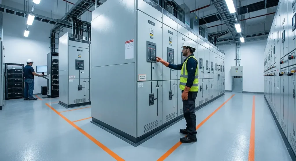
Dielectric insulation flooring serves as a vital safeguard in modern data centers which serve as the backbone of global digital operations. While substantial capital is invested in server rack cooling, redundant uninterruptible power supply (UPS) units, and physical security, the foundational surface beneath critical power distribution networks is often overlooked.
As AI workloads push power demands from 30 kW to over 100 kW per rack, rooms containing transformers, high-voltage switches, and backup batteries carry severe risks for technicians like- violent electrical arcs (arc flashes), dangerous electrical leaks, and electric shocks moving through the floor.
Standard raised computer floors are not enough, instead, facilities install seamless dielectric insulation flooring. Poured directly onto the subfloor, this specialized insulating material blocks high-voltage currents, resists chemical leaks from batteries, and withstands heavy machinery to keep workers safe
The Severe Operating Environment of Data Center Electrical Rooms
To select the correct technical flooring, engineers must evaluate the complex operational stresses inside power distribution quarters:
| Hazard in Electrical Rooms |
What Can Happen |
| High Voltage / Touch Risk |
Uneven voltage on the floor can create a serious electric shock hazard.
|
| Temperature Changes |
Repeated heating and cooling can cause concrete to expand, shrink and develop cracks.
|
| Oil or Chemical Spills |
Transformer oil and chemicals can damage ordinary floor surfaces and weaken the concrete.
|
| Heavy Equipment Loads |
Transformers and electrical equipment can create heavy point loads of up to 80 kN, damaging weak flooring.
|
1. Elevated Voltage Exposure & Step Potential Risks
When main power lines bring 11,000 to 33,000 volts into a data center, heavy transformers and switches handle immense electrical energy. If an electrical failure or sudden spark occurs, a massive burst of current shoots into the floor, creating dangerous voltage spikes across the surface. A technician walking across this area risks an electric shock simply from the difference in voltage between their two feet—a hazard known as step potential. Specialized non-conductive resin flooring creates a continuous insulating barrier over the concrete, blocking this current from traveling through workers and keeping high-voltage power rooms safe.
2. High Point Loads & Dynamic Heavy Equipment Movement
Switchgear cabinets, heavy transformer units, and modular UPS battery racks exert tremendous loads. During installation, expansion, or maintenance, heavy equipment is rolled across the floor surface using heavy-duty nylon wheels or air-caster skids. Conventional floor finishes fracture, spall, or delaminate under these high point-loads, creating surface fissures that compromise electrical isolation.
3. Chemical Exposure from Power Infrastructure
Lead-acid and liquid-electrolyte storage batteries release corrosive acidic vapors and accidental battery acid (sulfuric acid) drips. Additionally, mineral oils or synthetic ester fluids used in transformer cooling can leak onto floor surfaces. Unprotected concrete absorbs these liquids, degrading the structural matrix, introducing moisture pathways, and compromising the isolation boundary.
4. Continuous Thermal Exposure
Heavy electrical infrastructure emits continuous radiant heat. Floor coatings installed directly beneath power distribution units (PDUs) and transformer bays experience thermal aging. Over time, thermal cycling causes low-grade epoxies to embrittle, micro-crack, and fail.
Technical Baseline: Requirements for Data Center Electrical Floors
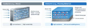
Dielectric insulating flooring acts as a high-resistance barrier to block high-voltage current flow and protect human life.
When specifying a dielectric insulation system for critical facilities, the following technical benchmarks must be met:
1. High Dielectric Strength & Breakdown Voltage (BDV)
Dielectric strength measures the maximum electric field strength a material can withstand without electrical breakdown (expressed in kV/mm).
- Breakdown Voltage (BDV): The total voltage at which the installed system fails and allows arc-through.
- Specification Requirement: Systems designed for 11 kV to 33 kV switchrooms typically require a factory-certified BDV exceeding 30 kV to 60 kV, verified under standard test methods such as ASTM D149 or IEC 60243-1.
2. Zero-Porosity, Pinhole-Free Matrix
In electrical isolation, a single microscopic air bubble, fissure, or pinhole acts as a path of least resistance for arc-discharge. Electrical fields concentrate at microscopic air voids via partial discharge, leading to premature insulation breakdown. Systems must be engineered with high vacuum-degassed self-leveling resins to ensure dense, pore-free consolidation.
3. Compressive Strength & Shore D Hardness
To prevent indentations from heavy equipment legs and moving wheel loads, the system must achieve:
- Compressive Strength: ≥75 to 85 N/mm² (tested via ASTM C579).
- Shore D Hardness: ≥80 to 88 (tested via ASTM D2240), demonstrating rigidity against mechanical gouging.
4. Flame Retardancy & Thermal Performance
Electrical rooms fall under strict fire-life safety codes. Dielectric Insulation floor coatings must exhibit low flame-spread characteristics, self-extinguishing properties, and compliant fire classification (such as UL94 V-0 ratings). The material must maintain dielectric stability at continuous operational temperatures exceeding 80°C to 90°C.
Engineering Mechanisms: How Dielectric Insulation Flooring Protects Facilities
Advanced poured resin systems—specifically solvent-free, highly cross-linked epoxy and polyurethane hybrid matrices—provide structural and electrical benefits across the data center ecosystem.
Eliminating the Weak Points of Insulating Rubber Mats
Historically, sub-stations relied on loose-laid electrical insulating rubber mats placed directly in front of switchgear panels. In high-density data centers, rubber mats introduce severe operational liabilities:
- Seam Vulnerability: Moisture, dust, and conductive debris collect beneath mats, creating tracking paths for electrical leakage.
- Physical Displacement: Wheel loads from maintenance carts buckle or dislodge mats, creating trip hazards and leaving floor areas exposed.
- Aging and Cracking: Ozone exposure and ambient heat cause elastomeric mats to harden and micro-crack over time.
A continuous, seamless poured dielectric insulation floor BONDS directly to the concrete substrate, eliminating seams, lap joints, and sub-surface moisture pockets entirely
Preventing Moisture-Induced Electrical Tracking
Concrete is naturally porous and contains free alkalis and moisture. Moisture vapor rising through a concrete slab (Moisture Vapor Transmission – MVT) carries dissolved salts to the surface. This creates a thin conductive film at the interface, causing electrical tracking along the floor slab.
High-performance dielectric systems utilize specialized low-viscosity, moisture-tolerant epoxy primers that penetrate deep into the concrete capillary structure. By sealing the concrete pores, the system prevents subterranean moisture from reaching the surface, preserving the non-conductive integrity of the upper body coat.
Seamless Chemical Armor Against Battery Acid and Transformer Fluids
Solvent-free aromatic/aliphatic polyurethane and modified epoxy-novolac resin formulations achieve extremely dense molecular cross-linking. When subjected to concentrated sulfuric acid spills in UPS battery rooms or hot dielectric oil leaks in transformer vaults, the resin matrix resists chemical attack. The chemical structure prevents surface softening or swelling, ensuring the dielectric breakdown voltage remains unchanged despite chemical contact.
Technical Specification & Performance Parameters
| Technical Parameter |
Standard Test Method |
Minimum Engineering Requirement |
| Dielectric Breakdown Voltage |
ASTM D149 / IEC 60243-1 |
15 kV to 60 kV
(Dependent on specified system thickness)
|
| Dielectric Strength |
ASTM D149 |
≥ 30 to 50 kV/mm |
| Compressive Strength |
ASTM C579 |
≥ 80 N/mm2 |
| Tensile Strength |
ASTM D638 |
≥ 25 N/mm2 |
| Flexural Strength |
ASTM C580 |
≥ 35 N/mm2 |
| Shore D Hardness |
ASTM D2240 |
85 – 88 |
| Flame Retardancy Classification |
UL94 |
V-0 (Self-Extinguishing) |
| Volume Resistivity |
ASTM D257 |
> 1013 Ω·cm |
| Surface Resistance |
IEC 61340-5-1 |
> 1012 Ω/sq |
| Abrasion Resistance |
ASTM D4060 (CS-17 wheel) |
< 35 mg loss
(1000 cycles / 1000 g)
|
| Water Absorption |
ASTM D570 |
< 0.1% |
Post-Installation Verification: Spark Testing and Quality Assurance
Installing a dielectric insulation system requires non-destructive high-voltage quality control testing after full system cure. Material spec sheets alone do not guarantee performance if pinholes or dust occur during application.
1. High-Voltage Holiday Detection (NACE SP0188 / ASTM D5162):
A high-voltage DC spark tester (holiday detector) is swept across 100% of the cured surface. The voltage is set slightly above the operational safety rating of the room. If a pinhole, micro-void, or thin spot exists, an electric spark arcs through the void to the concrete substrate, triggering an audible alarm for immediate repair.
2. Surface Resistance Verification:
Using megohmmeters with concentric ring electrodes according to IEC standards to verify that surface electrical resistance consistently exceeds 10¹²Ω across all zones.
3. Thickness Auditing:
Ultrasonic thickness gauges verify that the dry film thickness (DFT) meets the engineered profile calculated for the room’s maximum rated voltage.
Securing the Critical Layer
In modern hyperscale data center infrastructure, electrical reliability and safety cannot rely on secondary measures like loose rubber mats or untreated concrete.
By implementing a continuous, high-performance dielectric insulation flooring system, engineering teams build an impenetrable protective barrier. Combining high dielectric breakdown voltage, mechanical compressive strength, and chemical resistance, these seamless surfaces insulate technicians from high-voltage hazards, prevent electrical tracking, and safeguard data center uptime for years to come.
Conclusion
The Floorkrete® Electrogard® range is purpose-built to meet these stringent operational requirements. Formulated to deliver ultra-high dielectric breakdown voltage, superior compressive strength, and exceptional resistance to battery acid and transformer oils, Electrogard® creates a seamless, pinhole-free insulation layer across your entire floor slab. Every system undergoes rigorous post-application high-voltage testing to guarantee zero pinholes and continuous surface resistivity, keeping technical personnel safe from step-and-touch potential hazards.
Electrogard range:
- Electroscreed– 2-Part Dielectric Insulation High Voltage Resistant Self Smoothing Epoxy Floor Screed
- Electrogard ELI– Two component epoxy electric insulation coatings with UV resistance
Securing your data center’s power baseline requires engineering precision from the ground up. Choose Floorkrete® Electrogard® dielectric flooring systems to achieve certified electrical protection, superior durability, and uncompromised uptime for your critical infrastructure
FAQ